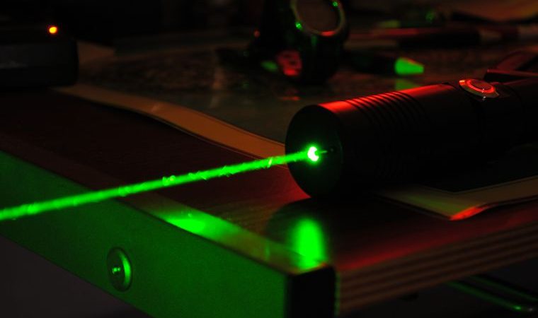
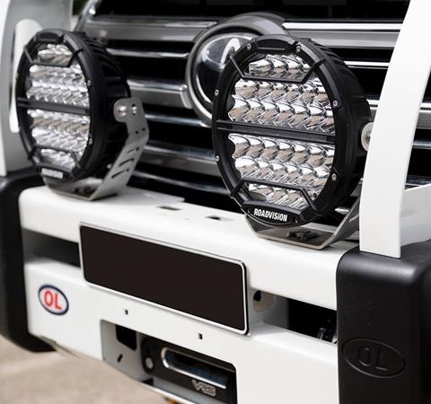
The laser and opto Web site
AquaLynx , detailed description for under water viewing.
Return to home page
Return to Gated viewing
 
There are two basic parameters that characterize an underwater vision system: limiting distance
and resolution. The principal limit of the limiting vision distance is exponential light decay with
distance (L) I~I0 exp(-e L), caused both by light absorption (k) and scattering (s) in medium in
such a way that index of decay e is equal to the sum of indexes of absorption and scattering
e=k+s. The light decay in water depends on the radiation wavelength and has a characteristic
minimum in a green-yellow range of spectrum. The existence of the green-yellow window of
transparency in water determines the optimum spectral range of light sources and receivers. Table
2 represents typical mean values of e corresponding to minimum of spectral response for various
regions.
Special feature of water is its significantly greater decay in comparison with atmosphere
(ewater/eatm)~10 3 , that is a result of the fact that density of water is greater that of atmosphere by
factor of 10 3 . Therefore is the vision distance in atmosphere can reach tens of kilometers, in water
in can be tens of meters and exceeds 100 meters in a pure water.
Existing underwater vision systems can be separated into two classes, passive systems operating
under natural illumination at shallow depths, and active systems using additional light sources
operating both in a continuous and pulsed mode. The present report describes a newly developed
system of underwater vision that can operate in a passive mode and in an active mode, exactly, in
an active-pulsed mode with a temporal gating or temporal cut-off of a back scattered background.
In the matter of fact, when using an active illumination it is necessary to solve problems with the
suppression of a background illumination connected with the light scattered back in the medium.
This share of light reduces the signal-to-noise ratio, image contrast and limits the maximum
accessible vision distance. A scheme of back scattering suppression is based on the spatial
selection of zone of observation (see fig. 1). The selection is carried out either by geometric
spacing of the light source and receiving camera or by the temporal cut-off of the background
signal when using pulsed light sources. In a mode of operation with temporal cut-off of the back
scattering interference, the receiving camera is always shut and opens only at the moment when
a useful signal enters. This is the mode that is realized in the vision system under consideration.
Let us take a look at the mode. A light pulse with a duration of the, spatial length of l=c tu,
propagating with an illumination angle ail, is emitted at the moment of time t0 (see fig. 1). As the
light pulse is propagating in water a light share, defined by the receiving angle are, is scattered
back from the illuminated layer of water and falls into the receiving camera. But during all this
time the receiving part of the camera is shut and only at the moment of time t1, when a useful
signal reaches the camera it opens and stay opened for a duration of the gate pulse Dtgate.
Therefore, only a layer of water of Dl=l/2 c Dtgate in depth at the distance of L=l/2 c t can be seen.
Varying a delay between the moment of light pulse emitting and the moment of the camera
opening tl, one can vary the distance to the zone of viewing. It can be easily seen on the fig. 1, that
at presence of the gate the signal-to noise ratio is increased by factor of (S/s), where S is the total
area under the curve of the medium back scattering signal, and s is the area under the curve of
back scattering at the time range of (tl, tl+Dtgate).
The underwater vision system consists of three main parts (see fig. 2), namely, the emitting part,
the photo receiving part and a unit of image recording and processing.
The emitting part incorporates an emitter itself, a power supply unit and a cooling unit. The light
emitter is a Nd+3:YAG solid-state laser with frequency doubling (l=532 nm) encapsulated in a
sealed metallic housing with dimensions of 70x70x500 mm3. An optical system provided at the
emitter exit allows to vary the angle of illumination from 60o to several minutes. Distilled water is
used as a coolant.
The photo receiving part consists of an image intensifying tube with a micro channel plate (MCP),
conjugated with a CCD camera.
The receiving camera is capable of operating in two modes, passive and active.
The image processing system is made on the base of an IBM PC compatible computer. The image
is entered by means of a standard image input/output board.
Basic system parameters are represented in Table 1.

Table 1
CAMERA MONITOR LASER Weight, kg 3 7.5 12
Dimensions, mm (LxHxW) 170x160x105 , 310x215x215 , 380x90x275
Power supply 12 V (from the monitor)
AC 220 V, 50 Hz AC 220 V, 50 Hz
Resolution 400 TV lines 450 TV lines -Field of view 60 o F=14/2.3 14 o F=37/1.1 --
Minimum illumination 0.002 lx

The system was tested in the optical pool of the Institute of Physics of Belorussia. During the tests
special test objects with black and white hatching were used as objects of viewing to estimate the
system resolution. Maximum pool length is 40 meters, that factor defined the range of controllable
delays.
Investigations of the system performance in various media showed that the limiting vision
distance could be represented as t t = = e e Llim = 8, where t is optical density of water.
Or Llim = 1.8 zw , where zw is the depth at which a white disk of 30 cm in a diameter is not seen.
In a number of publications it was suggested to represent a relationship between the depth of the
white disk disappearance out of view and the index of light decay as e e zw= b b. A value of 4.7 - 5 is
considered to be the most probable value for b. Table 2 represents typical values of zw and
maximum accessible vision distances for various regions, resulting from the experimentally
obtained data for e Llim = 8.

Table 2
REGION e(m -1 ) zw(m) Llim(m) L'lim(m) (estimated)
Baltic Sea 0.5 9.4 17 28
Black Sea 0.3 15.6 28 44
Open Ocean 0.1 47 84 113
Sargassian Sea 0.07 67 120 153

Also shown in Table 2 are simplest estimations for the limiting vision distance at the camera
sensitivity of 10 -4 lx under the conditions of total suppression of the back scattering, that
High sensitive gating system of underwater laser vision Page 5 of 6
corresponds to the mode of gating and taking into consideration of only a single back scattering
when the process of light decay in water can be described by the law of Booger. In this case,
taking into consideration a geometry of illumination and registration, the illumination on the
photo cathode can be represented as follows:
Where P0 is the source power (3 MW),
r - reflection factor (0.5)
a - angle of illumination (0.5 o )
L - distance to the object
g - lens aperture (0.5).
Numerical values used in (1) correspond to the conditions of the experiment.
Results of calculations using (1) show that the increase of energetic parameters of the system
(sensitivity of photo receiving camera or light source intensity) of 10 times leads to the increase of
the parameter t = e L only by a unit. It means that for water having e=0.1 m -1 the distance
increases by 8 meters and by 2-3 meters for e=0.3 m -1 . This condition should be taken into
account in the design of vision systems in order to choose an optimum source energy and
sensitivity of the photo receiving camera.
In addition to the maximum accessible distance of vision a vision system is characterized by the
quality of image. The image quality is defined by the system resolution and image contrast. The
resolution of the camera is 400 TV lines at the contrast level of 0.1. For example, when operating
in water with e=0.36 m -1 or zw = 25 meters, the resolution drops down to 250 TV lines.
Use of the suppression of back scattering allows to double the vision distance as a minimum in
comparison with a static vision mode at the same active illumination.
The video signal outgoing from the camera is a standard broadcasting signal. This gives an
opportunity to record the image by means of a video tape recorder simultaneously with a visual
control. Additional signal processing is provided to improve the image quality. For this purpose a
computer based system of image input and processing was developed. The additional signal
processing allows to increase the image contrast and pick out a useful information against a
background of interferences.
2, 2 2, 0,680 g L, e P E L a p r e -2 = (1)
At present the developers work hard on the problems of vision system resolution increase and
reduction of power consumption and dimensions and weight of the system.

  1. Summary of all main products on one page .Links to pages .135 kb size . English version
  2. Summering av alla våra produkter. Länkar till relaterade sidor. 135 Kb dokument . Svensk text.
  3. Summary over our applications and solutions.
LaseroptronixAB
E-mail: info@laseroptronix.se
Telephone 46-70 714 04 70
Enhagsslingan 23
 Web site www.laseroptronix.se
187 40 Täby
VAT nr SE 556 569 1135-01 Laseroptronix is an AB organisation
Säte i Täby Kommun Glimmervägen 8 187 34 Täby / Sweden
Sweden North Europe
Navigation map of the site. Navigationskarta över vår webbsida
 Created 2005-10-27 by Allan Jansson

Keywords Gated viewing, laser camera active television , pulsed laser camera, ladar , lidar, laser radar image intensifier gated image intensifier . night vision camera gated camera time gated camera strobed camera strobed laser camera SAR, search and rescue , wire detection system helicopter airplane marine rescue see through snow , rain fog camera under water camera, under water viewing, see through camera, water penetrating camera, active laser gated camera, laser camera, sub merged